Show Posts

This section allows you to view all posts made by this member. Note that you can only see posts made in areas you currently have access to.


Messages - The Radio Shop

Pages: 1 ... 52 53 [54]
796
How CB radio works / Understanding how CB radio works
« on: January 19, 2011, 12:25:30 PM »
Ok, back to Getting to know you way around the radio

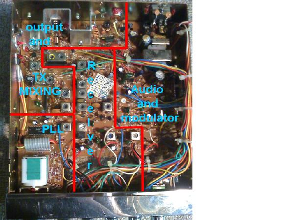
Please excuse the crude photo I am attaching.
As you can see I have divided the radio into 4 main groups. Remember, some sections do over lap with other sections. But that is fine for now. Mostly all radios today are built under this design. You will see a few that is a little different. But when you get the understanding of where things are in the Cobra 29 you will easily be able to identify other boards. In my first post is a schematic with certain area\'s labeled. Take the time to open that schematic and find the labeled sections on the schematic. That will give you a better understanding as to where the parts are in relation to the schematic.

PLL
In this area you will find the PLL chip and it\'s supporting components, 10.240 reference oscillator, The VCO and supporting components. You will also find the 5 volt regulator in this area.

Output and TX mixing
In this area you will find the begining of the transmit stage, the transmit mixer, predriver (buffer), driver , and the final

Audio and modulator
In this area you will find the audio stages, the AMC stages and modulation limiting circuits, voltage regulators for TX & RX functions..


797
How CB radio works / Understanding how CB radio works
« on: January 19, 2011, 12:24:53 PM »
Thanks Klondike Mike.

In the next few post I want to start with a new subject. Getting to know you way around the radio.  I will take a pic of the inside of a Cobra 29 and break it down into 4 quadrants.
PLL section
Transmit mixer
Receive and output
Audio section.

There are actually 5 sections. The fifth section which is the middle of the radio contains  IF filters, the AM  demodulator and the squelch circuits. But we will leave this section for a later time.

Once you know your way around the radio this makes repairs a lot easier.

798
How CB radio works / Understanding how CB radio works
« on: January 19, 2011, 12:24:28 PM »
The Dead Receiver

Over the years I have had several techs call me trying to figure out a simple problem. They tell me the radio transmits fine. Has full power and audio out. But the receiver is dead as a door nail. No RX audio, no deflection of the S-meter.  One tech brought 2 radios over for me to look at. Sure enough, both had dead receivers. After 5 minutes a piece, both radio\'s were working fine and the receivers was singing away. Both radios were Cobra units. One rig was used in a pick up by a deer hunter the other was used in a big rig.  Both units had the same symptoms but different problems. one the speaker jack had cracked loose from the main board. The other had a cracked solder joint in the RX section.

Both units had non working S-meters. This is what I call the hibernating receiver.
Get you a known working S-meter from an old radio. Attach red and black wires with alligator clips. Then when testing a radio just clip the S-meter in. This may save you many hours of hair pulling.

799
How CB radio works / Understanding how CB radio works
« on: January 19, 2011, 12:23:58 PM »
And Greetings to you  Handy Andy. I am honored that you chimed in. And please do so when ever you can.  

I agree on what you said there. Equipment is very expensive. And when on a budget, make the best of what you have.

 I am very old school myself.  Not very educated at that. So you want hear me using a lot of big words    Back in the day my work bench consist of a analog volt meter, (have to check those capacitors and transistors) soldering iron, and a SSB 23 channel radio as a test rig.  I took the SSB rig to a well known cb shop and had it tuned and aligned.  When tuning a am rig I switch the test radio to ssb and zero beat the signal to get the thing on frequency. That was the only thing I had back then to use as a frequency standard. I later converted and old RCA co-pilot (PLL 02A) to a signal generator.

Times have really changed since then. I will post a pic of my work bench again one day. But well after it is cleaned up.  Now my benches contain (3) B&K 2040 signal generators, Sencore CB 42, IFR 1200S service monitor, Motorola frequency/ auto tune deviation tone test rig, B&K 1801 and Heath 2410 frequency counters, Bell & howell scope, Kenwood SM 22- station monitor, and a Sencore SC61 scope. HP 3400RMS volt meter plus countless more pieces of test equipment.

But, all this is not needed for CB repair. I also repair business band radio and ham radio.  Anyone can become a decent repair tech if you stick with the basics, ei find what does work. Process by elimination.

Anyway, I am just an old country boy guys. Took a look in my first Cb radio when I was  12. I will do my best to work along with you guys to make this thread a learning experience.

800
How CB radio works / Understanding how CB radio works
« on: January 19, 2011, 12:23:23 PM »
On the bench at this moment is a Uniden PC 66XL. This is the same radio as the Cobra 25. I still use the basic 29 schematic theme when checking these radios.

This radio has the no TX or RX problem. I am not just talking about audio, but there is no detectable 27 mhz signal on TX or RX.  This is when your test radio comes in handy. Key the radio under test with the test rig set to the same channel. Do you hear a slight signal? Now key the test radio and listen to the rig under test, do you hear anything? does the meter move?


First test was at pin 2 of the PLL chip. I used a frequency counter to check the 10.240.  And there is was. Good
Next test was at pin 4 of the audio chip with a metal probe. Yep, plenty of noise.
Next I used my frequency counter to check TP 3. Set channel selector to 19.  There should be a 16.270 mhz signal there. Nope, counter reads zero. Now lets go to pin 10 of the PLL chip. This should give a frequency of 5.140. That is half of the 10.240...The PLL chip has a diver circuit that produces this signal so it is internal to the chip. As I test this pin I find no 5.140 mhz signal present. With this condition there will be no 16.270 mhz at TP 3 to deliver 1st mixer energy to the RX mixer.  And since the signal is not present at TP 3 or pin 10 of the PLL, then we determined that the PLL chip is bad.

This took about 4 minutes to check after the radio covers were removed and power was applied.
This is why I say it is easier to check what is working in a radio instead of spending hours looking for  the faulty component first.

801
How CB radio works / Understanding how CB radio works
« on: January 19, 2011, 12:22:10 PM »
Cool, Well we will get started with the basic stuff this week.

Some things are easy to fix. Say the radio transmits power but there is no modulation from the rig. You would start with the simple stuff like checking the mic. Or the radio meter moves on receive but you hear nothing coming out, you would check the speaker and the external speaker jack.

But what if the radio has no trans mit or no receive? Or worse yet has neither  ???  ???
Instead of going in and shot gunning the problem it would most likely be easier to find out what is working. But to do this you will need a few pieces of test gear to do so. a good DVV, frequency counter, watt meter dummy load, and a test radio. And dont forget the test equipment you were born with.
Your senses.  
Do you see anything out of the ordinary like burnt traces, blown components?
Do you smell anything burnt?
Do you hear anything when you transmit to or from the test rig?
If you touch components do they feel hot?
Do you taste ..opps, we want go there :)

See, a lot of times with just using what you have the problem may stand out in front of you.
When a radio comes in that does nothing but light up, the first thing I do is check the 10.240 mhz crystal oscillator. Lots of time I fine the problem there. If you find no 10.240 check the solder connection to the crystal.  Failure of the 10.240 crystal does happen often. If all good there go to IC 4 pin 4. This is the Audio amp. pin 4 is input and pin 9 is output. With a metal probe touch pin 4. If all is good you will hear a loud roar you can expect  the audio chip is good. If the chip is bad it can short the voltage to ground and stop many circuits from running. The voltage to the TA7222 is on pin 10.

802
How CB radio works / Understanding how CB radio works
« on: January 19, 2011, 12:21:13 PM »
If any are interested I like to start a thread on understanding how CB radios work. I have picked up some free time now and it may be something to help those that want to learn. There are a lot of folks here full of technical knowledge and I think this would be a good tread to help others that want to know learn and understand what is going on in these little set’s.  I see so many folks trying to troubleshoot radios and do not even know where on the board to find the problem let alone on the schematic.

What I like to do is start with a chassis like the cobra 29.
Post a schematic with the various stages marked.
Post a description of components and what they are. For instance;
TR 1 (RF AMP),
IC 3 (TX MIXER)
Ecx.

Just to give the guys that want to learn a bit of a heads up.
Then in the end discuss how to make your own test equipment like using the 29 as a signal generator


I have uploaded the modified schematic. This is not my work. It was given to me and I updated it.

803
Home Brew And Tech Forum / Simple transistor tester
« on: November 13, 2010, 11:14:54 AM »
Here is a simple circuit for testing NPN transistors

804
How CB radio works / Cobra Radio Stuff
« on: October 30, 2010, 05:23:23 PM »
Setting up a shop

805
How CB radio works / Cobra Radio Stuff
« on: October 19, 2010, 07:48:09 PM »
The 4 main sections of the radio

806
How CB radio works / Cobra Radio Stuff
« on: October 17, 2010, 03:29:16 PM »
I will post a series of stuff on how CB works. I will be using the cobra 29 as the model. This thread will be a sticky and locked. All questions and comments Will be in another thread.

807
RADIO MODS / Convert cb to different freq
« on: June 11, 2009, 10:31:54 PM »
This one works in the Cobra 29

Pages: 1 ... 52 53 [54]