Show Posts

This section allows you to view all posts made by this member. Note that you can only see posts made in areas you currently have access to.


Topics - The Radio Shop

Pages: 1 ... 14 15 [16] 17
226
CB Radio Repair Forum / Resting RF output on cobra 29
« on: June 25, 2014, 10:02:27 AM »
This shows various stages of RF output issues.
The blue dots on the schematic indicate in-out of each RF transistor

The screen shots of the scope shope base-collector open
base-colloctor short
proper amplification

227
Test Equipment / IFR 1200 checksum error fixed
« on: June 21, 2014, 09:22:57 PM »
After quite some time of this issue I finally resolved the checksum issue on this unit.
On boot up the unit would give an error. What I found was a battery on the CPU board was dead, Not having a solder in coin cell battery on hand I simply mounted a coin cell hold to the rear of the CPU board. Was not enough room to mount on component side.

The battery solved the boot up problem.

https://www.youtube.com/watch?v=S7U9EGVQwPM

228
Test Equipment / Areis A-PS30M supply
« on: June 20, 2014, 05:00:49 PM »
A off the wall supply

229
Test Equipment / Astron VS-50M repair thread
« on: June 18, 2014, 04:55:08 PM »
I will be posting the repair of a astron supply I picked up. ATM it has a blown SCR and the meter pegs when powered up. So either a series pass ot LM723 bad.
While checking the transistors they all read about the same.

Also noticed no thermal grease on transistors

230
Electronic videos / The dead receiver Tech tip
« on: May 31, 2014, 09:38:08 PM »
Here we look at a simple device for testing the "dead receiver" on a cobra 29 radio.
This radio actually has 2 problems that prevent it from receiving.

https://www.youtube.com/watch?v=K0BRiMj7JHg&feature=youtu.be

You can also use this on other types of receivers to test

231
Electronic videos / My first YouTube video HP 8640B signal Gen
« on: May 24, 2014, 06:54:52 AM »
https://www.youtube.com/watch?v=ZQrnKrwrBqE&feature=youtu.be

This is my new HP signal generator I purchased from a very nice fellow up in Pikeville.  He bought it 2 years ago and was going to fix it but never got around to it.  The unit is well used. And would not power up. While checking switched I noticedthe fine tune switch is stuck and I broke the FM mode switch. That can be fixed no worries.

I addressed  the no power up issue and found that one side of the power switch did not work.  Removed the switch, drilled out the rivits, and found a spring out of posistion on that side. Put it back together and the unit powers up.

Next was to remove the range select unit so I could address the cracked gear issue. It is simple to remove but I nned to take the front panel off also to repair the broken slide switch and do some needed cleaning.  While looking at the cracked gear I noticed one of the contact fingers were missing on the front rotory switch. I cut up an old relay to make the fingers out of, took me 2 tries to get it right.

After I get the unit cleaned up I will put everything back together and start testing to see where it is. I do know it put out some signal but with the fingers missing nothing was right.

232
Home Brew And Tech Forum / Kenwood ts-430s
« on: April 25, 2014, 08:48:30 AM »
Lots of solder problems on this one.

233
Manuals / B&K 1801
« on: March 18, 2014, 07:46:42 PM »
manual and schematic

234
Test Equipment / Com Ser Laboratories tear down possible repair
« on: February 23, 2014, 09:16:34 AM »
When I quit the commercial 2 way radio business (EF Johnson) I started doing more radio repair at home in the early 90’s. I was in need of a service monitor to generate and receive signals from and to the radio under test. I found this service monitor local and purchased it. The range is 0 to 999 MHz.  Just what I needed.  And with the scope and trouble tracer add on I was able to check CTCSS by watching the Lissajous patterns on the scope.

After a couple of years the magic smoke rolled out of the scope unit.  A quick tear down revealed one of the PIO caps had exploded.  0.1uf @ 2kv. Being so busy at the time I simply unplugged the unit and continued to work.  I think it was 7 years later the unit started showing its age.  The signal out became distorted and had low output.  This was time to start trying to obtain info on this unit.  So off on the internet I went only to find nothing.  Google search would not return anything on this unit.  The only name branded part in the machine was the RF attenuator made by WaveTek. So I looked them up and ordered the precision resistors that were in the unit.  The guy I talked to said that Com Ser Laboratories was sort of a fly by Night Company and was bought out by another company.  Never did find out who that was. 

Later in December of 2007 a friend of mine that travels found a guy out west that had the same unit less the scope attachment.  He was able to scan the schematics to Adobe and emailed them to me. These looked like they had already been scanned many times and really did not have much info on them.  No part numbers or part locations. So if anyone has any other info on this please let me know.
I have placed the files on my website back then for download:
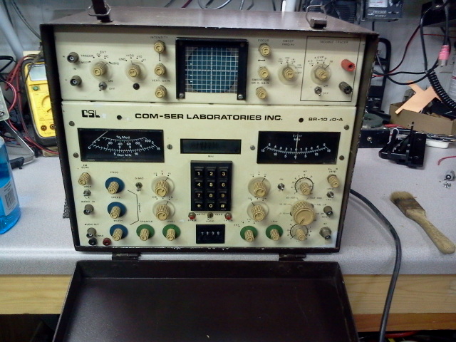
http://gokarters.com/smf/index.php?topic=1736.new#new

The monitor as it looks:


Cover removed showing the rear of the unit. Here we can see the card tray that holds the boards. These use old style card edge connectors


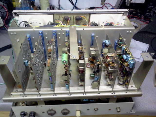
This is a view from the top showing card tray and between the tray and front panel is the mother board.
The first card is the 10 MHz crystal oscillator board.


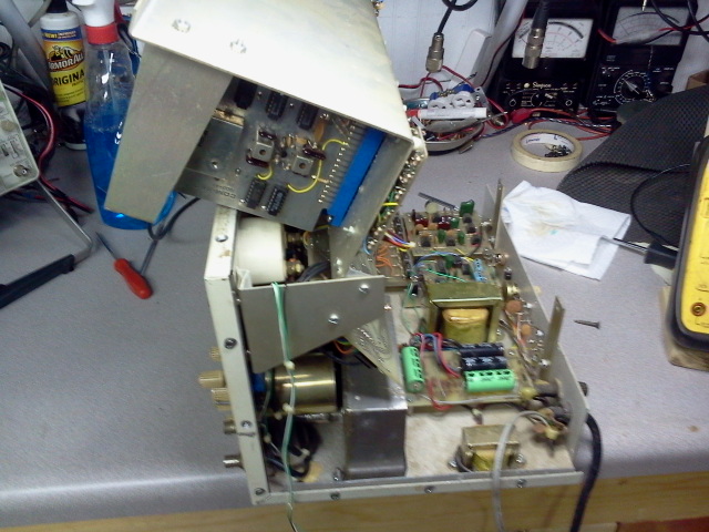
Here we have the card tray lifted up. It is hinged along with the mother board also.
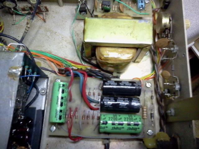
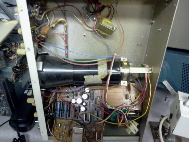
On the bottom of the chassis you can see the power supply.  This supplies:
5VDC
-5VDC
10 VDC
15VDC
-28VDC


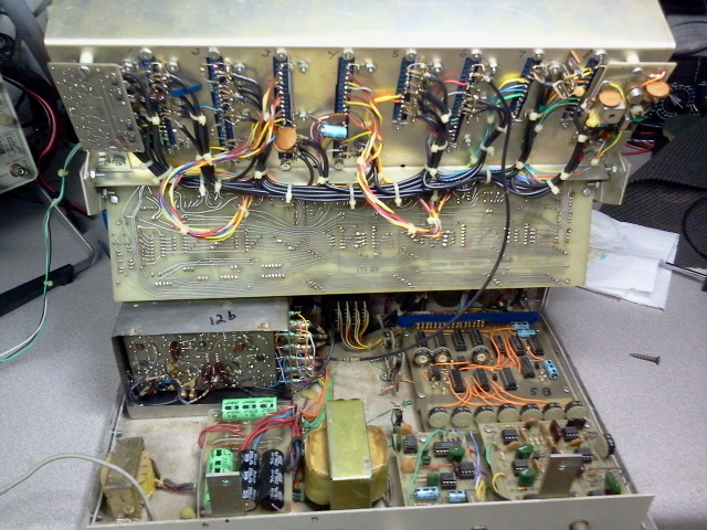
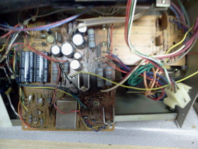
Here is a closer look at the power supply board


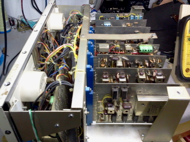
This image shows how the card tray pivots to allow service to the bottom of the chassis.
Also in the bottom lef you can see the bras cylinder. this is the WaveTek RF attenuator.


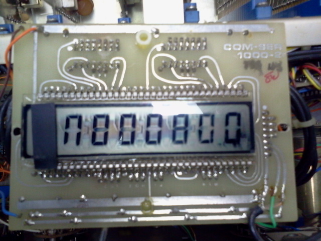
I am afraid this may be a problem. The display shows the digits, although it has no power applied.  If I can fix the unit I will have to come up with a new display.


This is the scope unit. It mounts on top of the generator.  I am guessing the engineering department knew nothing of heat transfer back then.  The main scope board mounts component side down.  So a lot of heat has been transferred to the circuit board and has chard the board.


Just a closer image of the scope board.


This will most likely be a tough repair, so will be working on it in spare time. First thing I want to do is check out the power supply and make sure everything there is up to spec.

Thought I share a bit here.

235
CB Radio Repair Forum / Cobra 2000 restore
« on: November 29, 2013, 03:17:48 PM »
Time to bring new life in an old radio

236
Signal Generators / Sencore CB42 manuals
« on: November 24, 2013, 06:45:01 PM »
In this thread I will start a repair series for the Cb42

The bottom manual has the color schematics.

237
Shop Talk / Shop tour
« on: July 02, 2013, 04:13:37 PM »
Just posting my stuff here.

238
Signal Generators / B&K 2040 thread
« on: July 01, 2013, 10:14:04 AM »
I picked up another B&K 2040 a whilke back I need to get going.
Last time I tested this unit it produced a wide signal on the output and no matter where you set the channel display out it was the same.  However the 455kc section operates as designed.

Someone added a multi 6 position switch to take this unit out of the normal band.  Most likely it has a VCO problem as the 2 10.240 oscilators are working.
I will be poosting my findings in this thread and have attached the service manual.

239
Trivia And Games / evony stuff
« on: June 28, 2012, 12:20:34 PM »
:)

240
CB Radio Repair manuals and documentation / CB Tune up mauals
« on: June 15, 2012, 08:56:09 PM »
Listed below are the Master CB tune up books.

Pages: 1 ... 14 15 [16] 17